Most contractors in Southend-on-Sea underestimate the complexity of the ground until the shoring starts to deflect. The town sits on an intricate geological boundary where stiff London Clay transitions into the water-bearing Thanet Sand Formation, often capped by a complex layer of made ground right along the seafront. A generic propping schedule simply will not hold up here. When groundwater levels rise—and they do rapidly in this coastal estuary environment, barely 3 metres below the pavement in some wards—the risk of basal heave or hydraulic uplift can compromise a standard retaining system within hours. The design must account for these layered conditions from day one; otherwise, the excavation becomes a reactive exercise in damage control rather than a controlled engineering operation. A solid CPT test programme across the footprint provides the continuous stratigraphic profile needed to calibrate wall embedment depths before a single bucket is dug, and the data feeds directly into the finite element models that anticipate wall displacement under tidal pore pressure fluctuations.
In Southend-on-Sea, a deep excavation design that ignores the tidal lag in the Thanet Sands can underestimate lateral pressures by up to 30%, turning a stable cut into a costly remedial operation.
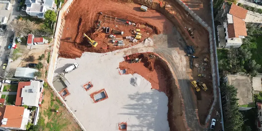
Local context
The engineering team mobilises a tracked CPT rig across the site—often a 20-tonne unit with hydraulic rams capable of penetrating the dense Harwich Formation—to ‘read’ the ground before the structural design begins. This machine pushes a 15 cm² cone at a constant 2 cm/s, recording tip resistance, sleeve friction, and pore pressure every centimetre; in Southend-on-Sea’s estuarine soils, the dissipation tests are critical because they reveal how quickly excess pore pressure bleeds off into the surrounding strata. If the data shows a perched water table within the made ground above the London Clay, the design must incorporate a discrete well system or vacuum-assisted drainage to prevent a sudden blow-out at the toe. The biggest hazard is not the clay itself but the buried channel deposits—remnants of ancient river courses now filled with loose silty sands—that can trigger a localised collapse during a heavy rainfall event. Combining the CPT profiles with a MASW survey helps identify these soft channels by mapping shear wave velocity contrasts, giving the structural modeller a three-dimensional picture of stiffness rather than a single borehole log. Without this multi-method characterisation, the excavation support system is effectively designed blind to the very features that cause progressive failure.
Common questions
How far must site investigation boreholes extend below the proposed excavation level for a Southend-on-Sea basement?
BS EN 1997-2 recommends that boreholes reach a depth of at least 1.5 times the excavation depth below final formation level, or 5 metres into competent strata, whichever is deeper. In Southend-on-Sea, where the Thanet Sand and Chalk interface often lies between 15 and 25 metres below ground, the investigation should extend well into the Chalk to confirm the absence of dissolution features or open joints that could compromise a toe embedment. The exact depth is agreed during the ground investigation specification phase, based on a preliminary desk study of the British Geological Survey mapping for the specific postal district.
What is the typical design life required for a permanent retaining wall in Southend-on-Sea?
Permanent embedded retaining walls are designed for a 50-year service life in accordance with BS EN 1990 and the UK National Annex, assuming the structure is classified as Consequence Class CC2. For highway-related structures or infrastructure with higher consequences, a 120-year design life may be specified. The durability design addresses sulphate attack from the London Clay—classified as Design Sulfate Class DS-2 to DS-4 depending on the location within Southend—and chloride exposure from airborne sea spray in the seafront wards, requiring specific concrete mix designs and increased cover to reinforcement per BS 8500-1.
How much does a geotechnical design for a deep excavation project in Southend-on-Sea typically cost?
The design fee for a deep excavation in Southend-on-Sea generally falls between £1,810 and £5,760, depending on the excavation depth, wall type, number of construction stages, and the complexity of the groundwater regime. A straightforward single-level basement in competent London Clay sits at the lower end, while a multi-level cut-and-cover scheme with tidal groundwater interaction, 3D corner effects, and adjacent heritage structures attracts a higher fee due to the intensive finite element modelling and sensitivity analysis required.
What monitoring is legally required during a deep excavation near Southend-on-Sea's listed buildings?
Building Control and the Party Wall Act typically require a detailed monitoring scheme when excavating within the zone of influence of neighbouring structures. The design team specifies precise levelling points on adjacent façades, inclinometers behind the retaining wall, vibrating wire piezometers to track pore pressure drawdown, and vibration monitors set to thresholds derived from BS 7385-2. In Southend-on-Sea, where many seafront properties are of traditional masonry construction, the peak particle velocity limit is often restricted to 10 mm/s for continuous vibration and 15 mm/s for transient events, with trigger levels set at 50% of these values to provide early warning before cosmetic damage occurs.